![]()
![]()
In this article I would like to show you how you can build the popular Pagoda antennas for less than $2. To do this, we simply order 160 PCBs via Seeedstudio for less than $40.
Note: Before I receive any additional e-mails and comments, that this article already exists at fishpepper.de (in English), please read the note of thanks at the end of this article. Thank you!
Why are the Pagoda antennas so popular?
The Pagoda antennas have an almost perfect separation from left-turning to right-turning signals, which means that these are ideally suited for FPV races.
The pilots should to fly on the raceband frequency band. From channel to channel, you should also change between RHCP and LHCP Antennas.
For example:
Pilot 1 – Raceband Channel 3 -> RHCP
Pilot 2 – Raceband Channel 4 -> LHCP
Pilot 3 – Raceband Channel 5 -> RHCP
Pilot 4 – Raceband Channel 6 -> LHCP
and so on…
![]()
Furthermore, these antennas are, with a material price of just $2 per piece, unbeatable cheap and each of us can order and solder the individual parts.
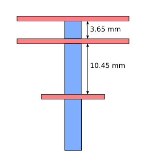
Unfortunately, these antennas also have a weak point and that is the three plates and the respective soldering on the cable. The antenna can no longer transmit / receive perfectly even with a slight degree of deflection of the plates (bending of the cable), since this can only be ensured if the plates are parallel to another. In addition, the RG402 cable easily breaks at the solder points. For this reason, it is important to protect the antenna sufficiently, because after the first crash, your picture will otherwise be much worse!
So think in advance about a reansonable protection and do not fly without!
I will try to build these antennas also with other cables, and also e.g. with a U.FL connector. For the protection of the antenna I will test with different materials like liquid rubber, 3D-printing parts as well as other solutions like foam to create a robust antenna. I will report on my progress below.
What we need
Ordering Pagoda antenna
We order the antenna plates via a large PDB manufacturer in China. The online form allows you to complete your order in a few seconds.
Seeedstudio
Go to the Seeedstudio Fusion PCB page.
Upload Pagoda design
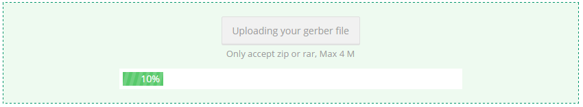
Via „Add your gerber file“ you upload the first ZIP archive.
![]()
I created both a design for RHCP and one for LHCP, which you can download here.
If you place an order using this article and/or with my design, this is at your own risk!
![]()
![]()
From the zip-file you need:
for RHCP the following three files
- part1rhcp.zip
- part2rhcp.zip
- part3.zip
for LHCP the following three files
- part1lhcp.zip
- part2lhcp.zip
- part3.zip
![]()
Check the PCB design
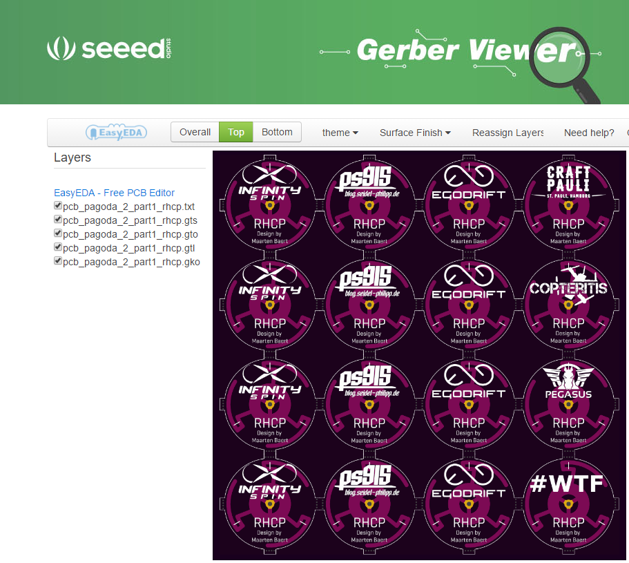
After the upload you can look at the design again in a viewer.
Click on „Gerber Viewer“
![]()
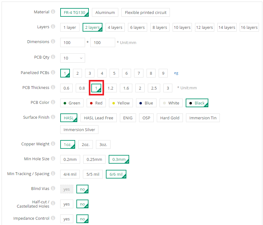
Specify production settings
Next set the settings for the PCB. It is very important to change the PCB Thickness to 1 mm. Under PCB Color you can select your desired color.
![]()
Place PCB in the shopping cart and complete the order
After you have all three ZIP archives (with the same settings) in your shopping cart, you can complete the order.
Make sure you set the correct settings for each ZIP archive!
![]()
Warning: Production error at Seeedstudio
It may happen that the ring for the ground is not separated from the signal on the bottom of the first PCB. This is a production error by Seeedstudio and will be replaced (hopefully) if you contact the support by e-mail.
![]()
If you have received faulty boards, these should not be used without modification, since otherwise there will be a short circuit in the antenna. The plates can be easily repaired with a metal drill. Thanks to Ronny for the photos and the hint.
Use a metal drill to drill the PCB
![]()
After drilling, the PCB should look like this. Now the plate can be used as usual.
![]()
Now I wish you a lot of fun with your new antennas!
If you have finished it, I would be happy you post a photo of it in the comments or on Facebook.
Create your own design – a difficult task
Creating your own design for the antennas was not as easy as I initially imagined. It took me many hours to figure out how it works. With the help of a few people from the FPV community, I finally succeeded. In the following, I would like to explain with a few pictures of how I created the design. This is not a step by step guide, but only roughly explained, because there are still many small difficulties, which I can not possibly all mention in this post.
Your logo on your antenna?
If you want to have your own logo on the antenna, but it is too difficult for you, I can gladly take over this for a €-fee for you. I only provide the ZIP file with the logo. The final ordering of the antennas must be done by yourself. -> Contact Form
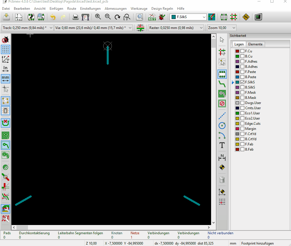
KiCad software
To edit only the Silk-Layer (font on the top) I downloaded the program KiCad.
Create design in black/white
First I created my logo as black and white PNG (with white background). As a format I have chosen 1468 px x 1468 px to get a relatively high resolution.
As an aid to the correct positioning of the logo on the antenna, I have inserted the outer circle, the antenna contour as well as the center point. These outlines will be removed at the end so that only the correctly positioned logo, the text and 5 small dots remain which help me with the correct positioning.
![]()
![]()
Design as footprint
Next, I converted the image into a footprint using KiCad. For this purpose it was important to adjust the resolution until the size of the image matches the actual size of the antenna. The purpose of this is that KiCad can not scale graphics or logos. That’s why you have to „hit“ the right amount beforehand. With a DPI value of 1655 I then hit the size of 22.5 mm (diameter plate) quite well and the image can be converted.
![Pagoda Kicad]()
Create KiCad footprint
Via the footprint editor I created a new module for each logo, which I stored in the KiCad library afterwards.
![Pagoda Kicad]()
Place footprint on Silklayer
The actual logos can then be placed. It is important to place the logos on the „Silklayer“.
![Pagoda Kicad]()
This is how it looks when all logos are aligned manually on the layout. A member from the FPV community was so nice and gave me the Silk layer with the alignment marks, so I had easier to position my logos (see above in the download). Positioning can be oriented either on the grid or can almost positioned freehand if the grid is adjusted very finely beforehand. The above-mentioned 5 points serve to position the logo precisely to the existing strokes. Alternatively, I would have to place the logos in the free space as best as possible, since there is no clue.
![Pagoda Kicad]()
![Pagoda Kicad footprints]()
Plotting and replace .gto file
The „plotting“ menu is used to create the .gto file, which contains the Silk layer information.
Now I replaced in the archive „pcb_pagoda_2_part1_rhcp.zip“ and „pcb_pagoda_2_part1_lhcp.zip“ the .gto file with my newly created file.
![Pagoda Kicad plotten]()
The logo is finished on the Silklayer! =)
I’ve never worked with a PCB software before, and I’ve had to research 2 full days to find these steps, as well as get help from the community.
Thanks again!
Delivery arrived
After about 30 days of waiting for the antennas the order arrived at me. The shipping takes 12 days and takes place in Germany by DHL.
Here are some photos of the antenna plates. My two logos (blog and InfinitySpin) I have now enlarged a littlebit, so that it can be plotted better.
![]()
![]()
![]()
![]()
![]()
![]()
![]()
![]()
![]()
Assembly Pagoda antenna
!! This area is not finished yet and is constantly being expanded !!
In the following article, I present the soldering aid made out of CFK designed by Klaus Krieber and me.
![]()
notes:
Assembly using 3D printing part: http://www.thingiverse.com/thing:2087305/#files
![Pagoda Montage]()
In the following video Maarten Baert shows in detail how to assemble the Pagoda antenna.
THANKYOU
I would like to thank the following persons